Before venturing any further in chronicling tele-tech bindings, it is important to understand the forces at play in a telemark turn. For the average telemarker, this article fits in the too much information category but for do-it-yourselfers, this should prove helpful in determining the critical sweet spot of the cable pivot position.
Activity
The key to control with the telemark turn is balance. Balancing between your two feet when dipping the knee is made easier with a spring tensioned cable attached to the boot. How much that helps, or doesn’t, is commonly referred to as binding ‘activity.’ Charlie Ziskin, a Colorado Front Range tele guru with decades of experience defines activity as “the ability of the binding to ‘actively’ help break the bellows of the boot, so you’re feeling pressure through the ball of the foot, not the tip of your toes.”
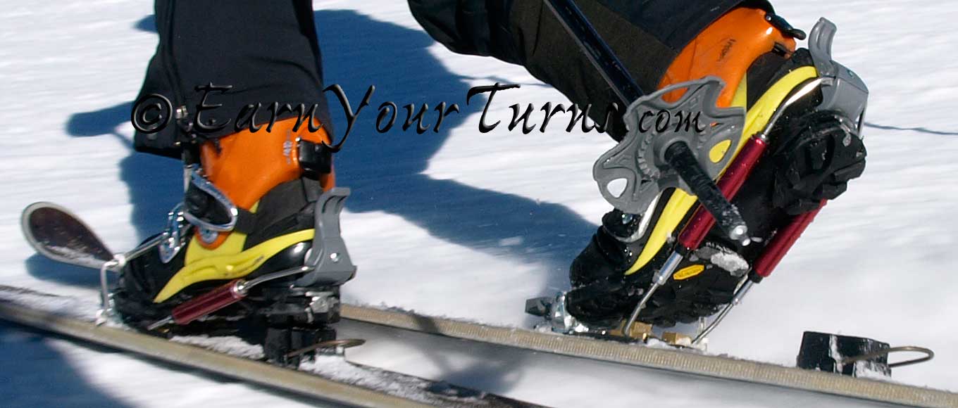
The effect of cable tension is a binding that actively helps to flex a plastic tele boot.
Cable bindings help break the bellows of the boot by providing a force to balance against. One of the results is increased tip pressure on skis; usually an advantage on hard snow and, without an adjustment to your tele stance, a potential liability in deep pow.
Regardless of whether more or less activity is desired, more active bindings have cable pivots that are further back than neutral bindings, with stiffer springs adding more force to the equation.
Vector Modeling
To understand what is going on, it helps to create a simple model of the components. When you sketch it out, the cable can be represented as a vector with a direction and force that resists the act of lifting the heel of your boot. The more you lift the boot and compress the spring, the more force is created, which augments flexing the rear boot in a tele turn. Looking at it this way, it is easy to see how the cable position and spring rate affect the perceived ‘activity’ of the binding.
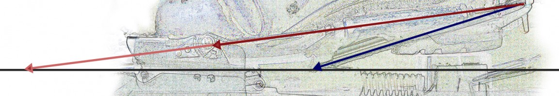
Comparing cable positions and angles for Voile’s Switchback (red) and 22 Designs’ Axl (blue).
Consider 22 Designs Axl and Voile Switchback as examples. The reputation for these two bindings are at opposite ends of the activity spectrum, with the Switchback being a ‘neutral’ cable binding and Axl, the free-pivot descendant of the Hammerhead, the epitome of adjustability and the benchmark of comparison for tele power. In the case of DIY 2-pin tele bindings, the potential for even more adjustability and/or activity exists but there are practical limits.
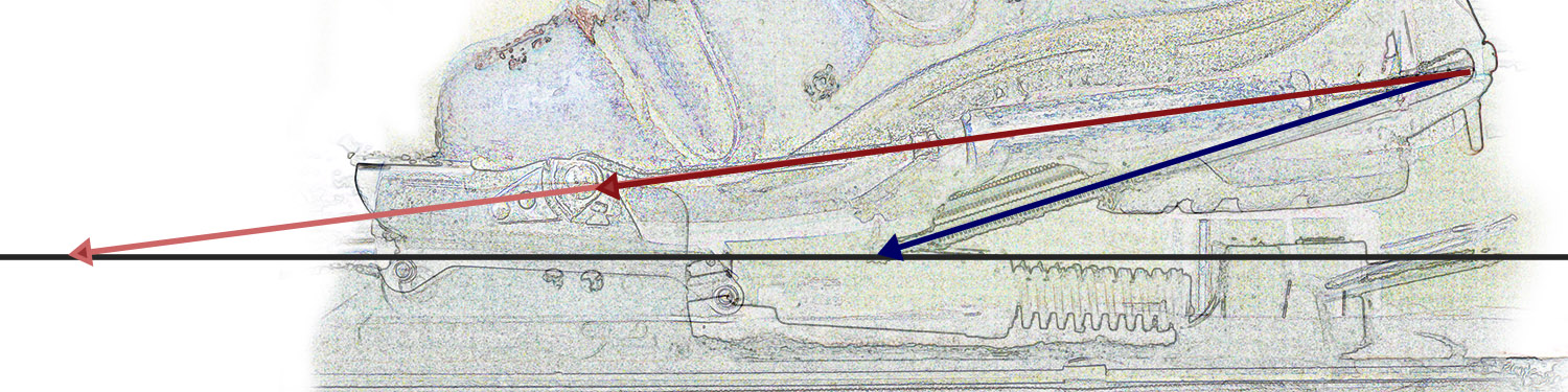
If you take a snapshot of the cable position from the side, the angle of the cable defines the direction of a vector with a resistance to change determined by the stiffness of the spring; the stiffer the spring, the stronger, bigger, longer the vector.
Resistance to heel lift can be determined with a lil’ trigonometry by splitting the vector representing the spring force of the cable into vertical and horizontal components. Analyzed this way it is easy to see why the Switchback is more neutral than an Axl in position 3 (or 2 or 1). For an equal spring rate, the percentage of resistance felt with Axl #3 (HH #5) is higher than for a Switchback.
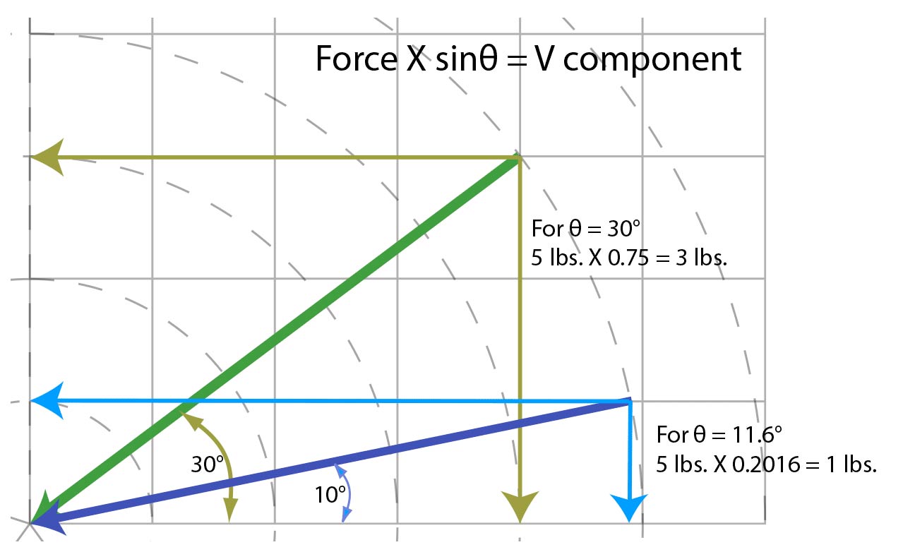
The steeper the angle, the larger the vertical component of force (resistance to heel lift)
otherwise known as activity. (Angles shown are simple examples, not measured values)
Angular rate of change
The tension starts out small but grows as the boot is lifted. The increase in force is because the spring is being compressed, but the rate at which it increases is due to the angle of the cable based on the pivot location and boot connection point. As the boot is rotating through a fairly large radius, defined by the length of the boot, the cable is rotating through a smaller circle which causes the rate of angular change to be much faster than the boot angle. Therefore, not only is the vertical component of the spring tension higher for any given boot angle, but it grows more rapidly the further behind pin line the cable pivot point is. This translates into faster engagement and higher activity.
Comparing the rate of angular increase.
For approximately 20° of heel lift, the Switchback cable changes 21°, Axl 25°.
Up/Down, Fore/Aft
In the world of DIY TTS systems it then becomes easy to conceptualize where to put the cable pivot, and how that location is affected by its horizontal and vertical position relative to the toe pins. The further back and below the pins, the stronger the vertical component will be. According to Pierre Mouyade, Meidjo’s inventor, “2mm of horizontal change is like 1mm of vertical.” That may not be a totally accurate formula, but it’s a good rule of thumb.
The reality is, for any given toe there is more latitude to adjust horizontal than vertical position. Tech toes that are higher, like G3’s Ion, inherently offer more vertical adjustment which mandates some sort of shimming at the cable block. Alternatively, if you want to increase vertical adjustability with a low tech toe (classic Dynafit), you will need to shim not only the cable block but the toe unit as well.
In other episodes of these 2-pin Tele Chronicles we recommend mounting positions for the cable, some examples, and other considerations.
Related Posts
DIY 2-pin Tele Chronicles: State of the Art
DIY 2-pin Tele Chronicles: Picking your toes
DIY 2-pin Tele Chronicles: Spring size matters
© 2017
Recent Comments